Table of Contents
Getting started – Riverdi GUI design with TouchGFX Designer
TouchGFX Designer is an advanced PC GUI-builder and simulator for STM32 microcontrollers from ST Microelectronics. It is ready-to-use solution to design stunning GUI.
TouchGFX in this example 4.20/1.10.1 is fully compatible and seamlessly integrated with all Riverdi products based on STM32H7.
Learn how to create GUI for your Riverdi display.
First, you need to install software and create a new project:
1.Install latest TouchGFX, CubeIDE and Cube Programmer into default location: available here
2.Start TouchGFX Designer
3.Create your project by clicking “Create New”
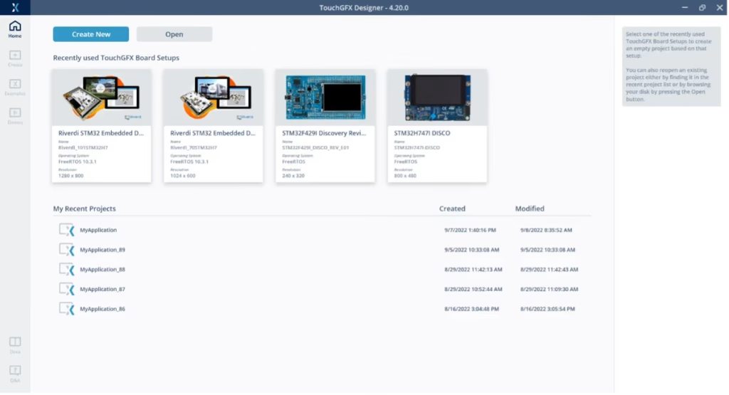

4.Go to “By Partners” tab to choose Riverdi display compatible project
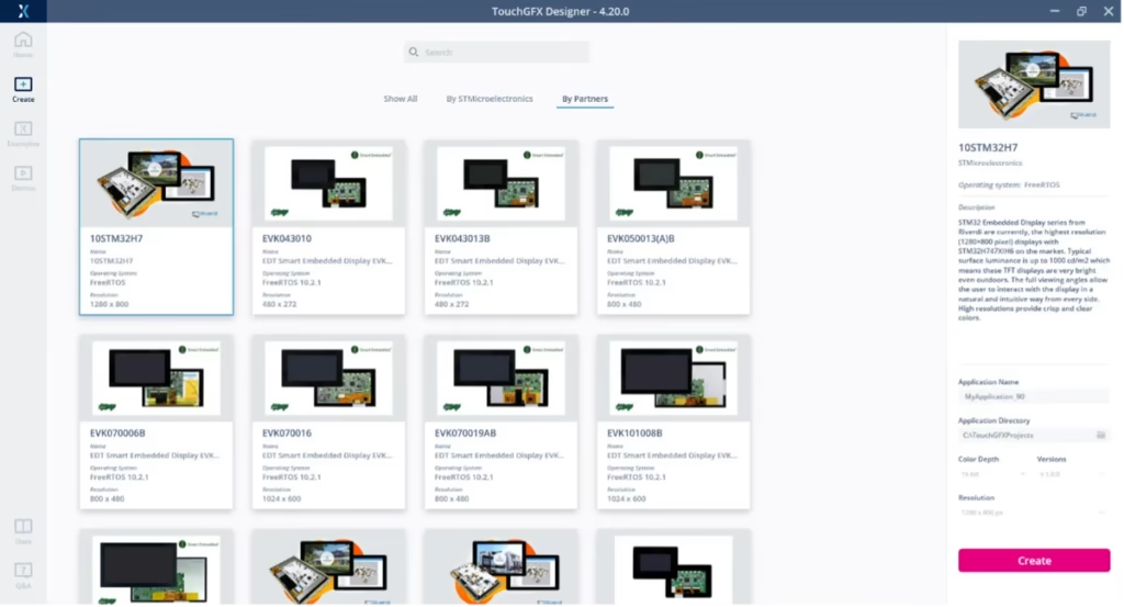

5.Select Riverdi board.
NOTE: There might be more than one template for the same Riverdi Display. Always select the latest version. Check the template details shown on the right panel. (In this case it’s v 2.0.1)
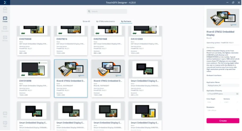

6. Click “Create”
Now you have an empty Canvas to design your GUI. You can put widgets using drag and drop from the menu. For example buttons, sliders, progress bars, images.
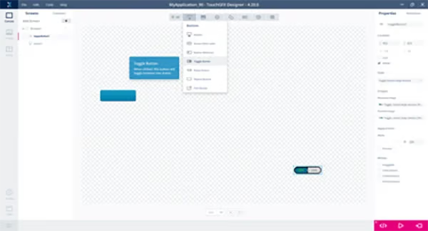

Once you have finished designing your GUI you need to:
1. Save the project.
2. Click “Generate Code” on the right bottom corner (or press F4).
TIP: You can check how your GUI will look like without connecting real hardware. To see how it works run the simulator by clicking play button on the right bottom corner (or press F5).
When you are happy with your project it’s time to make it work on your display:
1. Connect ST-Link programmer to PC
2. Connect SWD cable to Riverdi display
3. Confirm that you have a STM32H_IPS_QSPI_Loader_CM7.stldr file in
C:\Program Files\STMicroelectronics\STM32Cube\STM32CubeProgrammer\bin\ExternalLoader or path where you have CubeProgrammer installed.
If not copy it from generated project from \STM32CubeIDE\CM7\Stldr\ or \gcc\ folder
This is one time job so no need to overwrite it when you create new TGFX projects or modify existing one.
4. Connect power
5. Press “Run on Target” (or press F6)
TouchGFX Designer will compile project and create binary code. It will also automatically upload FW to Riverdi Display. Once this process is finished you should have your GUI running on actual board. Thanks to WYSIWYG (What You See Is What You Get) environment you don’t need to know any programming languages or hardware structure to create great GUI design.
Need some inspiration? There are demos!
Check out the Riverdi demo GUI project (IoT Smart Home):
1. File-> New
2. Select “Demos” from icons on the left
3. Go to “Board Specific Demo”
4. Select latest demo for your Riverdi Display
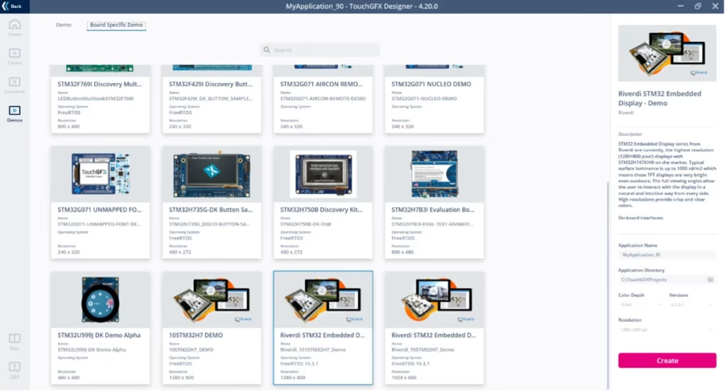

5. Click “Create”
6. Have fun and see how it works
7. To run it on a hardware display click “Generate Code” (or press F4)
8. Connect your display
9. Click “Run on Target” (or press F6)
NOTE:
Source codes generated by TouchGFX Designer contain IOC project file that can by open with CubeMX.
Unfortunately, as for now, re-generation directly from CubeMX is not fully supported. IOC project describe pinmux of GPIOs and how they are connected to interfaces. It also shows clocks and peripheral’s properties.
How to solve STM32H7 blocking due to incorrect configuration
Problem Overview
The issue here is that the MCU comes with an internal converter and LDO. The hardware design is not the same when it works with SMPS or with LDO. On our boards it is selected by resistors R44, R45 and R46.
By default we have LDO trim enabled, which means that R44 and R46 are not mounted, and the R45 is 0R. The processor blocks itself, if it initializes with a configuration different from the hardware.
It prevents the processor from self-destruction. Then the SWD is also blocked. The method used to fix this is issue depends on the board revision.
SOLUTION
There are 4 ways to reset this mode, choose one of them:
A) Enter the boot mode by performing following steps:
- Turn off the power
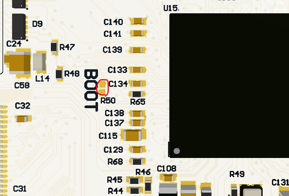
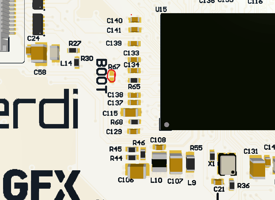
- Short BOOT pads (see the image below), You can use tweezers or soldering iron
- Turn the power back on
- Connect the SWD and perform full chip erase
- Turn off the power
- Un-short BOOT pads
For 10.1″ (R50)

For 7.0″ (R67)

B) Remove the R45 0R resistor, solder R44 and R46 with 0R. Then connect the SWD, clear the flash, and switch back the resistors.
or
C) Hold the processor reset and try to connect before the flash program reaches the PWR configuration. It takes only several dozen of ms, so you might need couple repeats to nail it. Then connect the SWD, clear the flash.
NOTE:
Remember to keep in your projects default power configuration:
HAL_PWREx_ConfigSupply (PWR_LDO_SUPPLY);
NOTE:
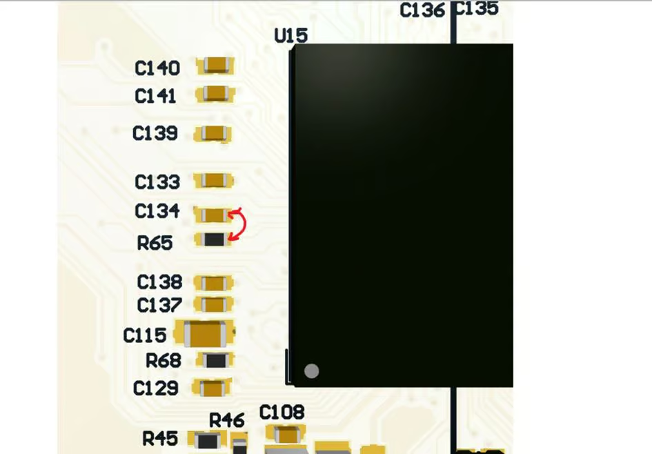
For older PCB versions option A is different
dir=”ltr”>A) Enter the boot mode by performing following steps:
- Turn off the power
- Connect the soldering pads R65 and C134 (see the image below)
- Turn the power back on
- Connect the SWD and clean the flash
- Turn off the power
- Disconnect R65 and C134
D) For 7-inch modules (revision 1.3 and later) and 10-inch modules (revision 1.6 and later), if the STM32H7 MCU becomes blocked and cannot be accessed, follow the steps below to unlock the MCU:
Press and hold the RESET button and BTN2 simultaneously.
Release the RESET button while continuing to hold BTN2.
Release BTN2 after the RESET button has been released.
After a successful connection:
Perform a full chip erase if necessary.
Reflash the MCU with the correct firmware.
Verify that the device is operating normally.
Debug configuration for CubeIDE for project with assets in external flash
After creating a project in TGFX and importing it into the IDE
You need to open the debug configuration window
Run menu ->”Debug Configurations…”
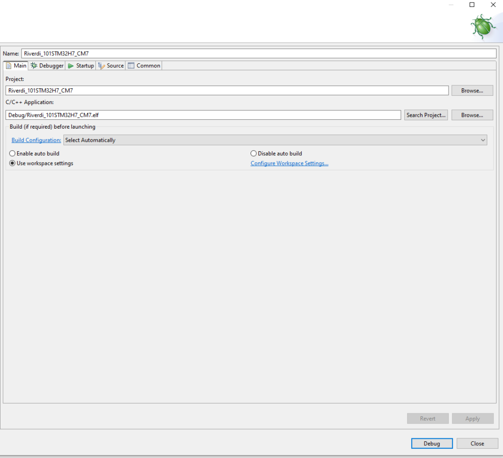

Then the “Debugger” tab
External Loader” section, click “Add”
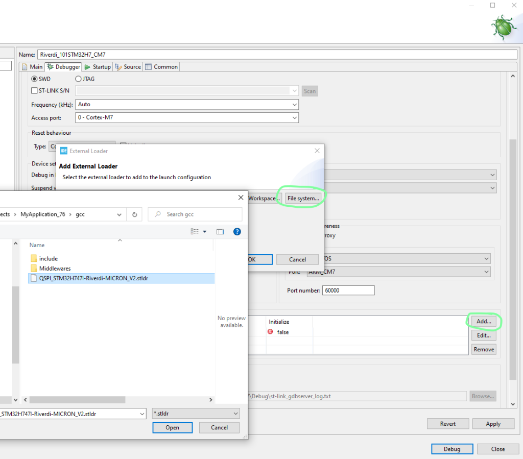

Then “File system…”
And point to the loader file.
At the moment you have to manually specify the full path. In the new TBS stldr will be added to the IDE project so it will be accessible from workspace and you won’t need to do this step
The “Enabled” box is to be checked and “Initialize” unchecked
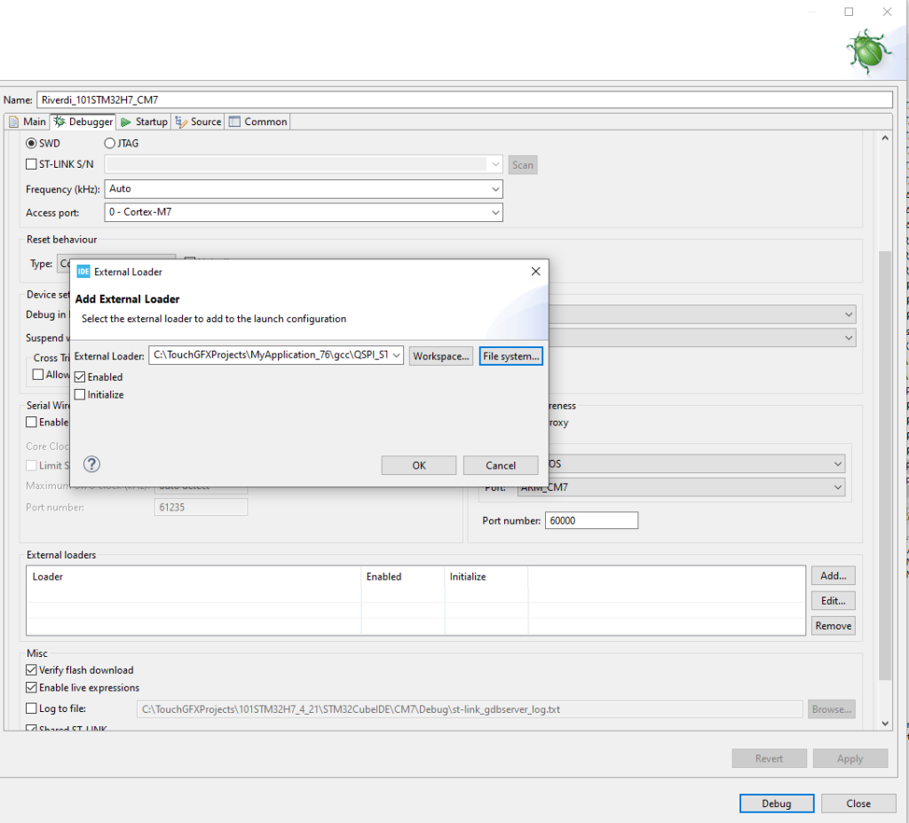

Click OK
And then Apply and Debug.


DISCOVER OUR
Whitepaper
Achieve the perfect user-display interaction with the right Touch Sensor IC. Ever faced issues with phantom touch events or certification? Boost your R&D like a pro with our Whitepaper!
