The tutorial provides an in-depth walkthrough on implementing the STM32-U5 embedded display from Riverdi in a project, showcasing a 5″ LCD TFT display from Riverdi’s new lineup, which is built around the STM32U5 series MCU renowned for its advanced power-saving microcontrollers.
Tutorial – Creating visuals for ADC potentiometer with Riverdi STM32 Embedded Display
By incorporating a capacitive-touch user interface developed through TouchGFX, the tutorial outlines how to visualize variations in an analog signal (from a potentiometer) on the graphical user interface (GUI), by configuring the ADC peripheral, coding, and integrating task and queue management with FreeRTOS in the STM32CubeIDE environment. Detailing each step, from configuring the MCU with cubeMX, coding the ADC task, interfacing and updating the GUI, to the final flashing of the project, the tutorial highlights a streamlined development process which directly regenerates projects using cubeMX, overcoming hassles experienced with previous Riverdi STM32-H7 embedded displays, and ultimately yielding a responsive gauge and voltage display in the GUI that adapts to potentiometer adjustments.
This tutorial is made by Controllerstech – Robotics Simplified, an India based software development company. Their goal is to provide software knowledge for microcontrollers based on STM32. Below we present the guide originally posted here: https://controllerstech.com/riverdi-stm32-u5-embedded-display/
Watch the video tutorial:
Riverdi STM32-U5 Embedded Display
This is another tutorial covering the STM32 embedded display from Riverdi, and today we have a 5″ LCD TFT display from their new lineup. Riverdi is specialised in manufacturing different kind of displays, which includes the STM32 based displays that supports the TouchGFX out of the box. The display can be purchased from https://riverdi.com/product-category/stm32-embedded-displays
This display is built around STM32U5 series MCU, which offers advanced power-saving microcontrollers, based on Arm® Cortex®-M33 to meet the most demanding power/performance requirements. Offering up to 4 Mbytes of flash memory and 2514 Kbytes of SRAM, the STM32U5 series of microcontrollers takes performance to the next level.
I have already covered few tutorials on the Riverdi STM32-H7 embedded displays, where I showed how we need to copy the prebuilt project to a new location, then modify the project from cubeMX and only copy the required files to the original project. This process works but there is a lot of hassle if you want to regenerate the project from cubeMX.
BUT with this new lineup of STM32-U5 embedded displays, we can directly regenerate the project using cubeMX. We can even flash the project using cubeIDE.
In this tutorial we will read the Potentiometer using the ADC, display its variation on the Gauge and also show the ADC voltage on a text area. To do this we will build the GUI using the TouchGFX, then regenerate the project using cubeMX configuring the ADC peripheral, write the code and flash the project using cubeIDE.
Design UI on TouchGFX
Create the project using TouchGFX

- Click create to create a new project
- Search for the Riverdi to see the available boards
- Choose the display you have. I have the 5″ STM32U5.
- Give the name to the project
- Click create to create the project.
Add the Required Elements to the UI
Below is the image showing the final UI design.
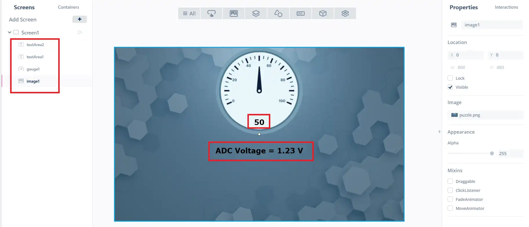
- I have added a Gauge, whose values can range from 0 to 100.
- TextArea1, which will display the value on the gauge.
- TextArea2, which will be used to display the ADC voltgae.
Both the Text Areas uses the wildcards, so we can update the values directly from the code.
After designing the UI, generate the project and open in the cubeIDE.
Configure the project in cubeMX
Below is the image showing the expansion connector pinout and how the potentiometer is connected to it.

We will use the ADC1 Channel 11/12, which is connected to the pin PA7 (pin 20). By default the ADC is configured in the differential mode, but for the potentiometer to work, we need to configure it in the single-ended mode.
Below is the cubeMX configuration.

I have reconfigured the ADC1 channel 12 in the single-ended mode. The ADC Resolution is set to 12-bit.
We also need to create a task and a queue to send the ADC data to the GUI. Below is the image showing the configuration for ADC Task.
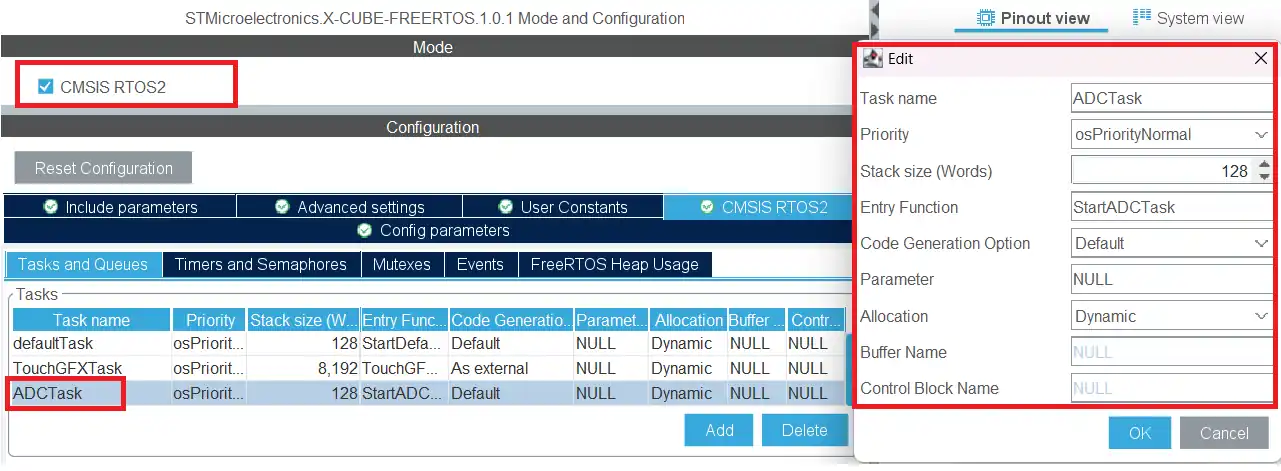
The ADC Task is configured with normal Priority. This will be used to read the ADC value and then send it to the queue.
We also need to configure the Queue to send the data to the GUI. Below is the image showing the queue configuration.
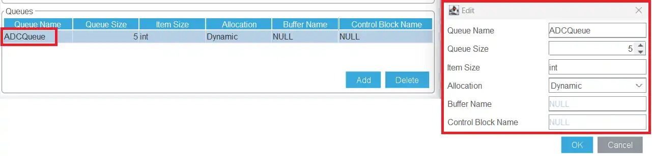
The ADC Queue is configured with 5 elements of integer size. We will send the values ranging from 0 to 100, so integer size is enough.
This is all the configuration we need, generate the project now.
Let’s write the Code
The ADC task we defined, can be found in the file app_freertos.c.
{
for(;;)
{
HAL_ADC_Start(&hadc1);
HAL_ADC_PollForConversion(&hadc1, 100);
uint16_t ADC_VALUE = HAL_ADC_GetValue(&hadc1);
HAL_ADC_Stop(&hadc1);converted_value = map(ADC_VALUE, 0, 4095, 0, 100);
if (osMessageQueueGetSpace(ADCQueueHandle) > 0)
{
osMessageQueuePut(ADCQueueHandle, &converted_value, 0, 0);
}
osDelay(100);
}
}
In the ADC Task, we will read the ADC value and then send it to the GUI using the ADC Queue.
- I am using the blocking mode to read the ADC value and store the value in the variable ADC_VAL.
- The ADC resolution is set to 12 bit, therefore the values will range from 0 to 4095.
- We will then map these values in the range from 0 to 100. The converted values will then be stored in the variable converted_val.
- Then we will check if the queue has some space in it. If there is space in the queue, send the value to the queue.
- This task will run every 100ms. We are just reading a potentiometer s timing and clock speed is really not the priority.
These values will be received in the GUI model. Below is the code showing the model implementation.
{
if (osMessageQueueGetCount(ADCQueueHandle) > 0)
{
osMessageQueueGet(ADCQueueHandle, &ADC_VAL, 0, 0);
}
modelListener->setADC (ADC_VAL);
}
Inside the model, the tick function is called with every frame refresh. We will check for the data in the queue inside this function.
- If the Queue has some data in it, we will read the data and store it in the variable ADC_VAL.
- This variable is defined in the Model.hpp.
- We will then call the function setADC in the modelListener.
The function setADC is defined in the modelListener.hpp file but its implementation should be as an empty function. This is shown below.
This empty implementation makes the GUI to look for the function inside the presenter file. This is where we will actually define the function.
{
view.setADC (val);
}
Inside the presenter, we will call the same function in the view.
The view is where the function is actually written. Below is the definition for the setADC function
{
Unicode::snprintf(textArea1Buffer, TEXTAREA1_SIZE, “%d”, val);
textArea1.invalidate();adc_voltage = (float)(val*3.3)/100.0;
Unicode::snprintfFloat(textArea2Buffer, TEXTAREA2_SIZE, “%.2f”, adc_voltage);
textArea2.invalidate();
gauge1.setValue(val);
gauge1.invalidate();
}
- Here we will first convert the value to the character format using snprintf, and then copy it to the textArea1 buffer.
- textArea1 is defined on top of the gauge, so it will display the values ranging from 0 to 100.
- Next we will convert the values to the float range of 0 to 3.3, this will be used to display the voltage on the ADC pin.
- Then convert the float value to the character format using the function snprintfFloat and copy it to the textArea2 buffer.
- textArea2 is defined below the gauge and it will display the values ranging from 0 to 3.3.
- Finally we will set the value to the gauge.
this completes our code part. Now we will flash the project from the cubeIDE itself.
Flash the project
We need to modify the debug configuration a little before we can proceed with flashing. The generated project from the TouchGFX does not generate the external loader file, so we need to provide its path relative to our file system.
Open the debug configuration, click on the debugger tab, scroll down to External Loaders.

Click on the loader and click edit.
Now click on file system.
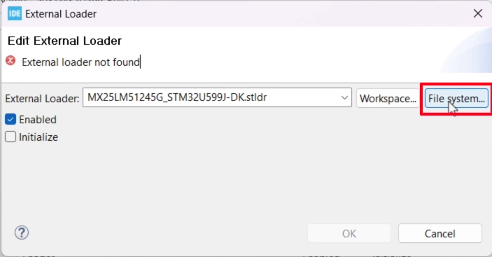
Now locate the loader inside the STM32cubeProgrammer directory. In my case it is located in Program Files -> STMicroElectronics -> STM32CubeProgrammer ->bin -> ExternalLoaders.
Once the loader has been located, click Apply to save the configuration, and click RUN to flash the project to the board.
Result
Below is the gif showing the display.
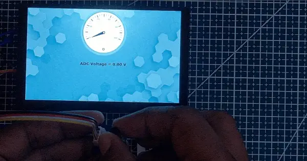
As you can see, the gauge is responding pretty well to the rotation of the potentiometer. The textArea on the gauge is showing the current value of the gauge.
The textArea below is showing the current voltage on the ADC pin, which can vary from 0 to 3.3V.
Download code
Here you can download the code shared by Controllertech: Potentiometer
Riverdi – the highest quality European display manufacturer
Why should you trust us and our products? Riverdi is the highest quality European display manufacturer. We have been producing TFT LCD displays for over 10 years, and have many customers worldwide to which we regularly deliver displays.
On our website you will find many series of different displays, but what we deliver is not only the highest quality displays, but also perfect documentation. On the website you will also find 3D models of every display, most of them come with an EMI report, so you learn about the emissions level. The order process is user-friendly, if you want to order a sample, you can buy it in our web shop. Just go to https://riverdi.com/product-category/stm32-embedded-displays/.
You can also contact one of our distributors. Riverdi has a wide distribution network including many US partners that can deliver the display to you at once.
Please remember to SUBSCRIBE to our YouTube channel and fill out the MEMBERSHIP FORM,
to stay informed about our Riverdi University materials and live events!
DISCOVER OUR
Whitepaper
Achieve the perfect user-display interaction with the right Touch Sensor IC. Ever faced issues with phantom touch events or certification? Boost your R&D like a pro with our Whitepaper!
Go to our product catalog and see how you can save by quality, not on quality.