In this Display 101 article we discuss the digital parallel RGB LCD display interface and how the row and column driving signals are generated from the digital parallel RGB interface.
TFT panel working principle
First, let’s introduce the basic working principle of a TFT panel.
An LCD display consists of an array of liquid crystal segments. The crystal itself doesn’t emit light. With no electrical field, crystals organize in a random pattern. When an electric field is applied, the crystals align to the electrical field. Various strength of electric fields works like a “gate” to pass different intensity of backlight through the crystals. If the crystals are aligned perpendicular to the backlight, then the backlight can’t pass through the crystals. [1]
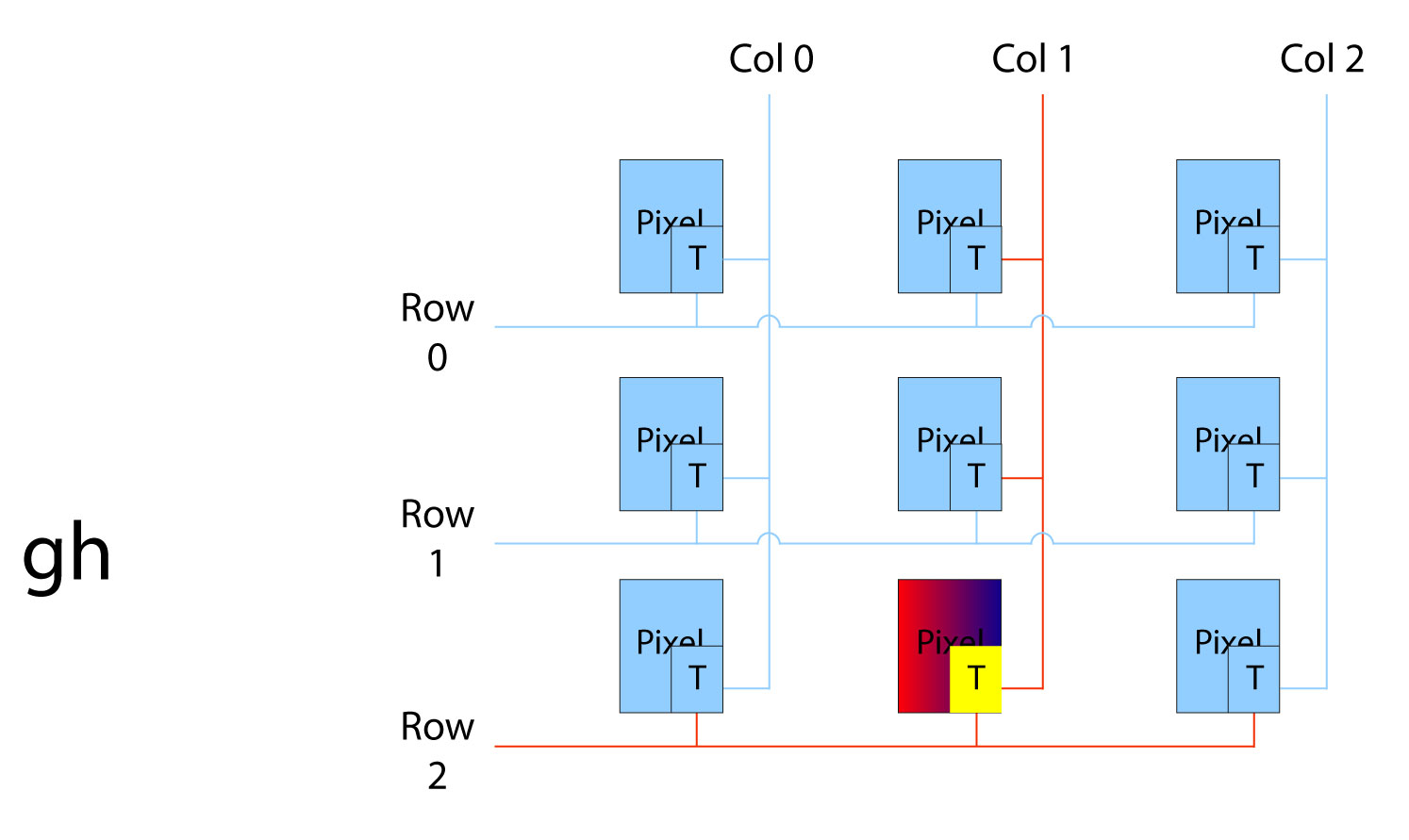
From the electronic structure point of view, an LCD panel consists of a grid of electrical signals. The pixels are addressed by a matrix where every interaction belongs to a pixel. Each pixel is connected perpendicularly to the row and column through a transistor. When the row and column are selected by an IC controller, the responding pixel at the interaction of the row and the column is enabled or disabled. [2]
Figure 1.1 The electronic structure of an LCD panel [2]
Generating a specific color for a pixel
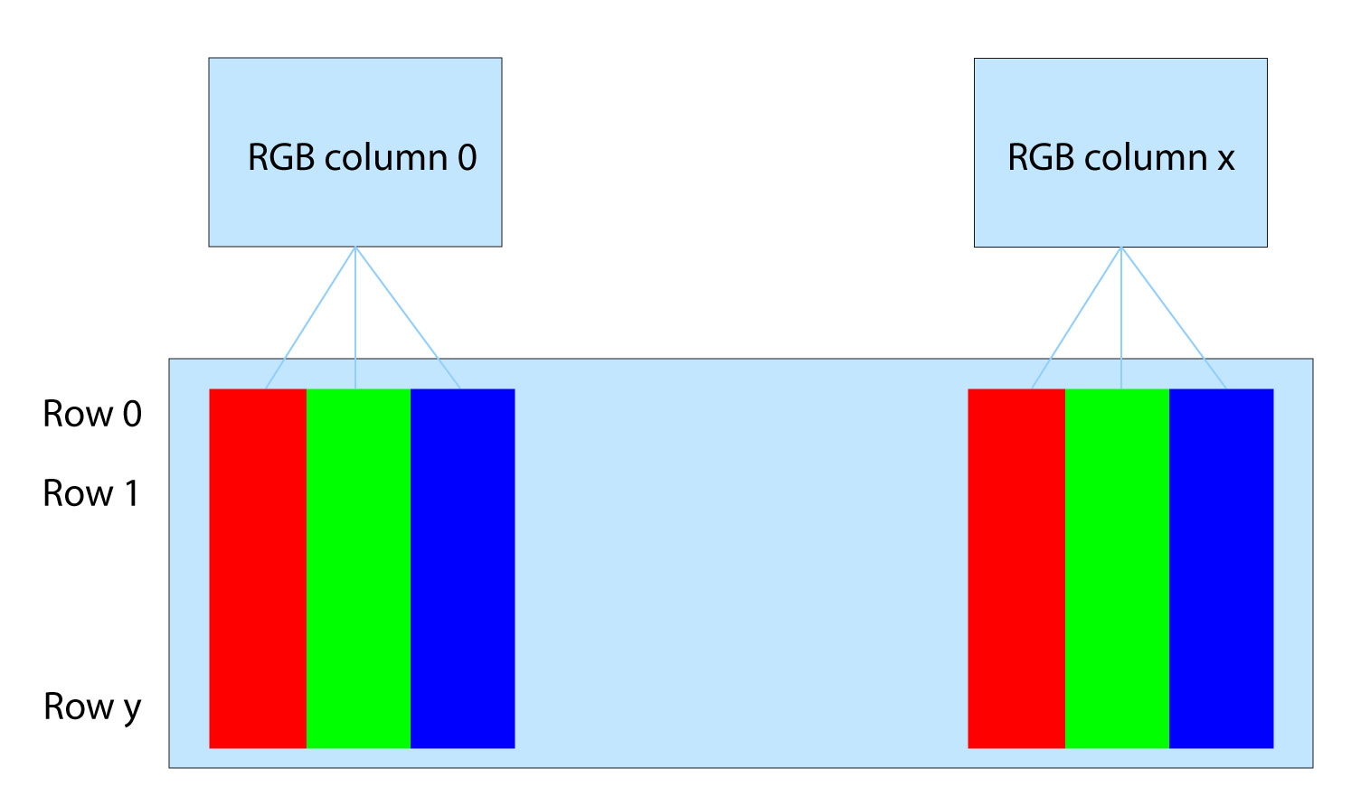
How to generate a specific color for a pixel? Each pixel is composed of 3 segments that individually pass light through a red, green, and blue filter, to make an RGB display color pixel. For a 320*240 RGB TFT display, there are 960 (320*3) columns and 240 rows.
Figure 1.2 The matrix arrangement of pixels of an RGB LCD display panel [2]
Most LCD displays have a digital parallel RGB interface. It works between the graphic controller as a signal source and the input of the RGB display module.
The RGB interface handles sending the image data information (grey level and color) in real-time.
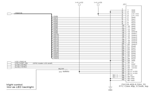
The image data is transmitted digitally as “0 “or “1 “ by TTL voltage levels. For the RGB interface, each of the signals has a corresponding line. Below are the signal connections of the LCD RGB display interface of 24 bits per pixel.
Figure 1.3 An example of TFT signal connections (24bpp) via parallel RGB interface [2]
What is a parallel RGB interface made out of?
The digital parallel RGB interface consists of the following basic timing signals: [3]
- VSYNC (Vertical Sync for TFT) is used to reset a new frame.
- HSYNC (Horizontal Sync for TFT) is used to reset the LCD next line or row.
- D0….dXX (every bit has a separate line).
- LCDCLK (LCD clock) is used to synchronize gray level data.
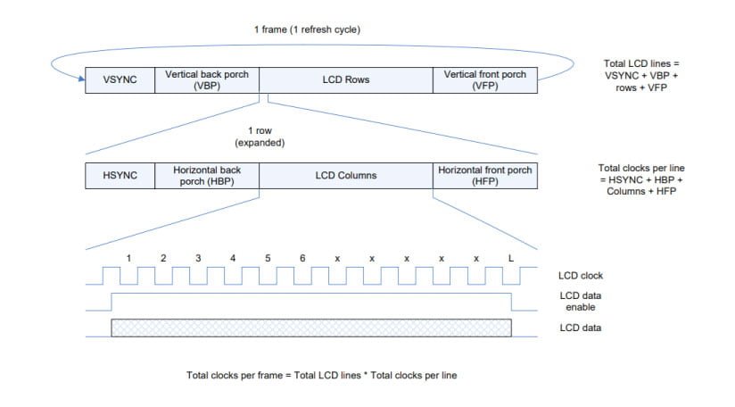
Figure 1.4. The frame and line timing parameters of a parallel RGB interface [2]
The vertical synchronization VSYNC sets the beginning of a new frame. There are no image data during the VSYNC sync pulse which are marked with VBP and VFP. [3]
The same principle is applied to the HSYNC sync pulse, marked with HBP and HFP. The HSYNC pulse is responsible for a new row. Between two HSync pulses, the grey level RGB color data for one row (line) needs to be transmitted. [4]
As the TFT display can drive 3 segments (1 pixel) per clock, the length of LCDCLK is determined by the number of columns of the resolution.
For example, the resolution of a TFT display is 480*272, then we assume the below parameters: [2]
| Vertical timing | Horizontal timing | ||
|---|---|---|---|
| VFP & VBP | 2 lines | H F P & HBP | 2 clocks |
| VSYNC width | 10 lines | HSYNC width | 41 clocks |
| Vertical period | 272 lines (vertical resolution = 272 pixels) | Horizontal period | 480 clocks (horizontal resolution = 480 pixels) |
Based on Figure 1.3 we can obtain:
- A single line takes (2 + 2 + 41 + 480) clocks = 525 clocks/line
- A full frame takes (2 + 2 + 10 + 272) lines = 286 lines/frame
- A full frame in clocks = 286 * 525 = 150150 clocks/frame
For a clock speed of 7.83MHz, the RGB LCD display would refresh at 7.83M/150.15K = 52.1Hz
References:
[1]: How TFT works. https://www.tomshardware.com/reviews/tft-guide,114-4.html
[2]: Philips. “Introduction to graphics and LCD technologies”
[3]: Chen, Janglin, Wayne Cranton, and Mark Fihn, eds. Handbook of visual display technology. Berlin/Heidelberg, Germany: Springer, 2016.
[4]: Watkinson J, Rumsey F (2003) Chapter 3: Digital transmission, Chapter 7: Digital video interfaces. In: Digital interface handbook. Focal, Burlingto
DISCOVER OUR
Whitepaper
Achieve the perfect user-display interaction with the right Touch Sensor IC. Ever faced issues with phantom touch events or certification? Boost your R&D like a pro with our Whitepaper!

