When you’re planning the design for an LCD housing you should follow a few basic principles, which we will explain in this Display 101 article.
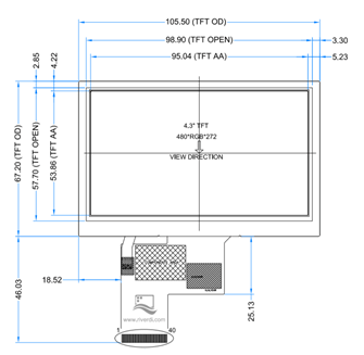
During the design phase of an LCD display housing, the most important parameters are the dimensions of the display and the location of the display area:
- Outline Dimension (OD) – external dimensions of the display
- Visual Area (VA) TFT OPEN – the visible area of the display, that you can reveal
- Active Area (AA) – the active area of the display, the place where are the pixels
The picture below shows the mentioned parameters:
Figure 1. The basic parameters of the displays
Important dimensions
If the window of the housing is bigger than the VA, it would reveal the metal frame of the display, and that would be very aesthetically unpleasing. On the other hand, if the window is smaller than the AA, we would cover the image displayed on the LCD.
Therefore, the most important dimensions from which we should start the designing of the LCD housing are OD, VA, and AA.
It’s worth adding that the display opening in the housing should be bigger than the external dimension of the LCD (OD) included in the drawing because the display can’t be placed tightly to the housing – that can lead to FFC tape or display damage. An offset of about 2 mm can be helpful.
When you’re designing the housing for an uxTouch module, you should pay attention to the dimension of the front glass (length, width, and radius of corners), the touch panel, the thickness of the glass and mounting tape. We offer uxTouch modules with various mounting tapes: 0.2 mm, 0.5mm or the custom thickness adapted for various applications.
Additionally, a very important factor is positioning the display relative to the touch panel.
For display modules with a mounting frame, the diameter and spacing of the mounting holes are important parameters.
All the dimension we mentioned above should be considered during the design of the LCD housing, which you will find in the technical drawing attached in the documentation of each module.
Figure 2. The important parameters for uxTouch module.


Figure 3. Important parameters for the module with a mounting frame
Assembling process
Following the correct assembling process of the module in the housing is crucial. During the wrong assembly process, very common damages are:
- damage of the FFC
- separation TP from TFT
- damage of the TFT glass
- bending of the LCD frame
In the first stage of mounting the module in the housing, you should put the edge of the FFC, and then carefully the rest of the module. This operation ensures you that the FFC will not be corrupted.
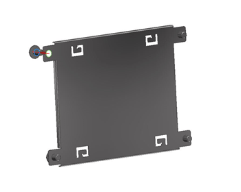
We recommend using support brackets assembled on the back part of the display. Additional support will stiffen the whole structure and minimize the influence of external factors, such as vibration and temperature variation.
Figure 4. Example of using support brackets
During the assembling the LCD in the housing you should be particularly careful not to use too much pressure on the module. In the case of mounting an uxTouch module, too much pressure will not help you get better adhesion.
DISCOVER OUR
Whitepaper
Achieve the perfect user-display interaction with the right Touch Sensor IC. Ever faced issues with phantom touch events or certification? Boost your R&D like a pro with our Whitepaper!


