Table of Contents
Screen rotation on Riverdi STM32 7” display
Screen rotation is a common requirement in STM32-based devices, especially when the mechanical design enforces portrait orientation or inverted mounting. On systems using the LTDC display controller, rotation must be handled in software, as the controller itself does not provide native framebuffer rotation.
This article explains a practical and commonly used approach to screen rotation on STM32 systems using TouchGFX and touch alignment, with optional panel-side correction when required by the physical installation.
Typical issues
Screen rotation issues usually appear as one or more of the following:
- the UI is displayed in the wrong orientation relative to the enclosure
- the screen content is readable only when the device is physically rotated
- touch input does not align with visible UI elements
These symptoms are not caused by display hardware faults, but by how orientation is handled in software.
System assumptions
This approach has been validated on a 7-inch Riverdi TFT display connected to an STM32 microcontroller using the LTDC interface. The described behaviour and configuration apply to this class of Riverdi STM32-based displays and are representative for similar setups.
How orientation is handled on STM32 LTDC
The LTDC peripheral scans the framebuffer in a fixed order defined by memory layout. It does not support rotating the framebuffer by 90 or 270 degrees in hardware.
For this reason, screen rotation on STM32 systems is typically divided into two independent aspects: the visual orientation of the UI and the mapping of touch coordinates. Each must be handled explicitly.
Recommended rotation strategy
A commonly used and robust strategy is to handle 90-degree orientation changes at the GUI framework level and apply an additional 180-degree correction only if required by mechanical mounting. This avoids runtime framebuffer rotation and keeps CPU and memory usage predictable.
Handling 90-degree orientation in TouchGFX
TouchGFX handles orientation by rendering the UI natively for the configured screen dimensions. A 90-degree change between landscape and portrait is achieved by selecting the appropriate width and height and designing the UI for that orientation.
The framebuffer itself is not rotated. Instead, the UI is generated directly in the required orientation.
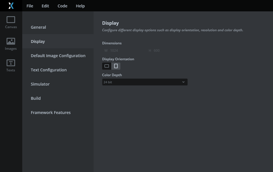
TouchGFX Designer showing project configured for portrait or landscape orientation
Optional 180-degree correction at panel or software level
In some designs, the display is mounted upside down relative to the intended UI orientation. In such cases, an additional 180-degree correction may be required.
This correction is not performed by the LTDC peripheral. Instead, it can be applied at the panel configuration level using display interface commands, or alternatively in software by applying coordinate inversion logic.
In the panel-side approach shown in the screenshot, the 180-degree rotation is achieved by a single change in the DSI panel initialization sequence.
Commenting out this specific DSI command (in this example line 250) that unlocks the panel control registers:
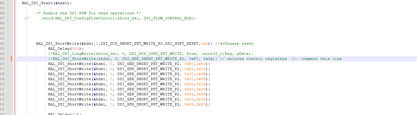
This causes the panel to operate with an inverted scanning direction, resulting in an effective 180-degree rotation of the displayed image.
No other changes are required in this sequence to apply the rotation.
This behaviour is panel-specific and depends on how the panel controller interprets its initialization commands. The change affects only the panel-side scanning orientation and operates independently of the LTDC framebuffer scanning process. It does not involve any hardware framebuffer rotation on the STM32 side.
When this method is used, touch coordinates must still be aligned separately, as the touch controller continues to report raw coordinates based on the physical orientation of the sensor.
Touch handling with LITEK ILI2132A in Riverdi IPS displays
All Riverdi IPS displays up to 10 inches use the ILITEK ILI2132A capacitive touch controller. When working with screen rotation on STM32-based systems, it is important to understand how this controller reports touch coordinates and how rotation must be handled.
Fixed raw coordinate reporting
The ILI2132A always reports raw, unmodified touch coordinates that are directly tied to the physical orientation of the touch sensor. The controller does not provide any configuration option to switch between portrait and landscape modes, nor does it support runtime rotation or 180-degree inversion of the reported coordinates.
There is no orientation or rotation register that can be used to inform the controller that the display has been rotated. Regardless of the screen orientation used by the GUI framework or display controller, the ILI2132A continues to output the same raw X and Y values.
This behaviour is by design and should be treated as a fixed characteristic of the controller.
Software-based touch rotation and alignment
Because the ILI2132A always reports raw coordinates, touch alignment must be implemented entirely in software. Screen rotation and touch mapping are two independent steps and must be handled consistently.
The recommended approach is to transform the raw touch coordinates according to the final screen orientation before passing them to the GUI framework.
First, determine the final screen orientation used by the system, for example native landscape, portrait, inverted landscape, or inverted portrait. This orientation is typically defined by TouchGFX project settings or by LVGL display rotation.
Next, read the raw touch coordinates reported by the ILI2132A. At this stage, the coordinates always reflect the native orientation of the touch sensor.
Then apply a coordinate transformation based on the selected screen orientation. The transformation depends on the screen width and height after rotation and typically involves swapping axes and inverting one or both coordinate ranges.
For example:
- with no rotation, raw coordinates can be used directly
- with a 90-degree rotation, X and Y are swapped and one axis is inverted
- with a 180-degree rotation, both axes are inverted
- with a 270-degree rotation, X and Y are swapped with the opposite inversion compared to the 90-degree case
Finally, forward the transformed coordinates to the GUI framework. In TouchGFX, this is done through the touch controller interface. In LVGL, the corrected coordinates are provided via the input device driver callback.
The GUI framework itself remains unaware of the physical touch orientation and always receives already aligned coordinates.
Rotation mapping reference
Assume:
- W is the screen width after rotation
- H is the screen height after rotation
- (x, y) are raw touch coordinates
- (x’, y’) are transformed coordinates passed to the GUI framework
Then:
No rotation (0 degrees)
Use raw coordinates directly:
- x’ = x
- y’ = y
90-degree rotation (portrait)
Swap axes and invert one axis:
- x’ = y
- y’ = W – 1 – x
180-degree rotation (inverted landscape)
Invert both axes:
- x’ = W – 1 – x
- y’ = H – 1 – y
270-degree rotation (inverted portrait)
Swap axes and invert the opposite axis:
- x’ = H – 1 – y
- y’ = x
These transformations are applied in the touch handling layer and do not affect display rendering.
Note on larger Riverdi displays
For larger Riverdi displays, a different touch controller is used. IPS displays above this size range typically use the ILITEK ILI2511 touch controller. While the general principle of separating screen rotation from touch mapping remains the same, implementation details may differ and should be verified for the specific controller and display configuration.
Verification
After applying the steps described above, the UI should appear in the correct orientation and touch input should align with UI elements. No runtime framebuffer rotation should be required. If touch behavior remains incorrect, axis inversion and resolution parameters should be rechecked.
Common pitfalls
Common issues include assuming LTDC supports hardware rotation, rotating the UI without correcting touch coordinates, and mixing panel-side inversion with GUI-level orientation changes without clear separation.
Screen rotation using LVGL
LVGL supports screen rotation in 90-degree increments. The orientation of the display can be changed using
lv_display_set_rotation(disp, LV_DISPLAY_ROTATION_xxx), where xxx is either 0, 90, 180 or 270.
When rotation is enabled, LVGL updates its internal coordinate system and swaps the horizontal and vertical resolution as required.
On STM32 systems using LTDC, rotation is handled entirely in software. LVGL does not rely on hardware framebuffer rotation. Depending on the selected rendering mode, pixel data can be rotated in the flush callback before being sent to the display. For rotated displays, LV_DISPLAY_RENDER_MODE_PARTIAL is typically used, as it allows individual rendered areas to be rotated before flushing.
This approach has been tested on STM32 systems with Riverdi displays using LVGL version 9.1 and newer.
Even when LVGL rotation is enabled, touch controllers continue to report raw coordinates. For Riverdi IPS displays using ILITEK ILI2132A, touch coordinates must still be transformed in software to match the selected screen orientation.
For more details on LVGL rotation modes, APIs, and examples, refer to the official LVGL documentation:
LVGL Screen Rotation
Summary
On STM32 systems using LTDC, screen rotation is handled entirely in software. TouchGFX is used to define the primary orientation by rendering the UI for the required screen dimensions, while additional 180-degree correction can be applied at the panel or software level when needed.
This layered approach provides a reliable and maintainable solution without relying on unsupported hardware framebuffer rotation and is suitable for long-term industrial applications.
DISCOVER OUR
Whitepaper
Achieve the perfect user-display interaction with the right Touch Sensor IC. Ever faced issues with phantom touch events or certification? Boost your R&D like a pro with our Whitepaper!
Go to our product catalog and see how you can save by quality, not on quality.