When designing electronic devices, you will encounter FFC (Flat Flexible Cables) and FPC (Flexible Printed Circuits). Both are flexible interconnect technologies, but they differ in construction, function, and applications. Understanding these differences is key to selecting the right solution—or using both together effectively.
FFC (Flat Flexible Cables)
Definition and construction (Parts and Materials)
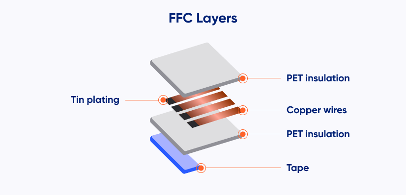
FFC cables are thin, flat cables used for standard signal interconnections. They consist of:
- parallel copper traces embedded in PET insulation,
- flat, symmetrical structure compatible with ZIF/LIF connectors.
The lamination process keeps costs low and allows fast production while maintaining consistent trace geometry.
Types and Operating Principle
FFC variants differ in:
- pitch,
- termination orientation: type A/B,
- length and number of conductors,
- flex rating – standard or high-flex.
FFCs act as simple, passive ribbons for short-distance signal routing.
Pros, cons, and typical applications
Advantages
- Low cost
- Very thin and lightweight
- Stable parallel traces
- Fast ZIF/LIF assembly
- Widely available
Disadvantages
- Only parallel routing
- Limited durability under repeated bending
- Cannot integrate components
Applications
- LCD/TFT modules
- Printers and laptops
- Household appliances
- Any low-cost, flat interconnections
FPC (Flexible Printed Circuits)
Definition and construction (Parts and Materials)
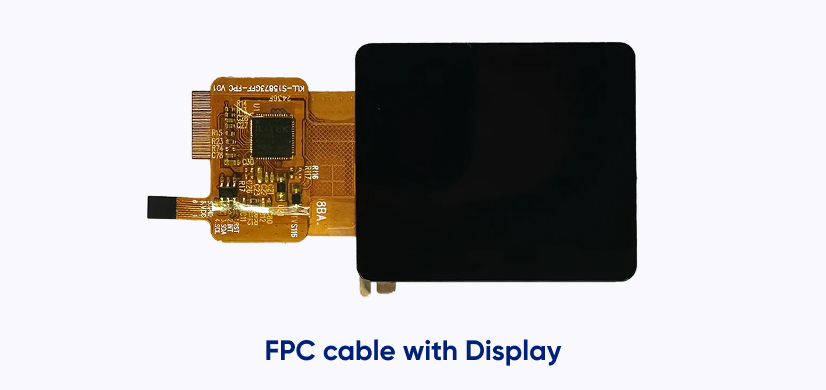
FPCs are flexible PCBs capable of carrying complex circuitry. They consist of:
- Polyimide (PI) substrate
- Copper traces etched in single- or multi-layer patterns
- Protective coverlay
- Pads, vias, or connectors for interconnection
FPCs combine the features of a PCB with flexibility and thin form factor.
Operating principle
FPCs carry power, signals, and may host SMD components. They can bend or fold to fit the geometry of the device, making them suitable for compact, integrated designs.
Pros, cons, and typical applications
Advantages
- Full routing flexibility
- Multi-layer and dense designs possible
- High bending endurance
- Thin and lightweight
- Can integrate components and connectors
Disadvantages
- Higher cost
- Longer production time
- Requires specialized assembly
Applications
- Smartphones, wearables, IoT devices
- Cameras and automotive electronics
- Medical equipment
- Miniaturized display modules
FFC vs. FPC: key differences and comparison table
| Feature | FFC | FPC |
| Construction | Flat cable with parallel traces | Flexible PCB |
| Material | PET | Polyimide (PI) |
| Customization | Limited | High |
| Trace complexity | Parallel only | Any pattern, multi-layer |
| Dynamic bending | Limited | Excellent |
| Cost | Low | Higher |
| Typical use | Simple interconnects | Structural + interconnect |

Comparison of FFC vs. FPC vs. rigid cables
| Feature / Property | FFC | FPC | Rigid Cables |
| Construction | Flat cable | Flexible PCB | Solid wire |
| Material | PET | PI | PVC / Teflon |
| Flexibility | Limited | High | Low |
| Routing complexity | Parallel only | Any | Limited |
| Production cost | Low | Higher | Low/medium |
| Typical use | Flat interconnects | Miniaturization + routing | General wiring |
| Dynamic durability | Low | High | Low |
| Assembly complexity | ZIF/LIF | Often soldered | Standard connectors |
| Advantages | Cheap, simple | Flexible, compact | Strong, inexpensive |
| Disadvantages | Simple structure | Higher cost | Rigid, limited flexibility |
How to choose between FFC and FPC
| Recommendation | Key Points |
| Use FFC if | – Connection is short and simple – Low cost and fast assembly are priorities – Minimal bending is expected |
| Use FPC if | – Flexible routing or multi-layer designs are needed – Connection moves during operation – Miniaturization and component integration are required |
| Combining FFC + FPC | – FFC connects main modules – FPC handles routing in tight spaces and tolerates repeated bending – Together, they improve device integration and reliability |
FFC and FPC are different, but should be treated as complementary technologies, selected according to the function within the module and the expected mechanical load. Contact our engineers to determine the optimal solution for your project.
DISCOVER OUR
Whitepaper
Achieve the perfect user-display interaction with the right Touch Sensor IC. Ever faced issues with phantom touch events or certification? Boost your R&D like a pro with our Whitepaper!
Go to our product catalog and see how you can save by quality, not on quality.