Table of Contents
How to change display backlight intensity in USB-C modules ?
Introduction
This manual explains how to change the display backlight intensity in different USB-C modules.
Types of modules classified by size.
The modules are divided into two groups: 10″ and 12.1″. The 10″ group includes six module types, while the 12.1″ group includes five.
Below is the list of 10” modules:
RVT101HVUNWN00
RVT101HVUFWN00
RVT101HVUNWCA0
RVT101HVUFWCA0
RVT101HVUNWC00
RVT101HVUNWC00-B
Below is the list of 12” modules:
RVT121HVUNWN00
RVT121HVUFWN00
RVT121HVUNWCA0-B
RVT121HVUFWCA0-B
RVT121HVUNWC00-B
Changing the display backlight intensity USB-C
There are two ways to adjust the display backlight intensity in USB-C modules. The modules are powered directly via the USB-C cable, so no additional power supply is required.
The backlight intensity can be adjusted either through the 6-pin Molex connector labeled “EXT PWR”, which provides PWM functionality, or via the USB-C cable using a terminal application, i.e. PuTTY.
When using the USB-C control method, first identify the COM port assigned to the connected device. Then, connect to this COM port using the terminal application. Once the connection is established, the backlight intensity can be changed by sending the appropriate command.
Commands are sent as ASCII strings in HEX format, using the following structure:
“AARRVV\r”
where:
AA – USB-C device address
RR – register address
VV – register value
\r – carriage return
Example:
“050432\r”
05 – USB-C device address
04 – backlight register address
32 – register value, corresponding to 50%
\r – carriage return
Example values that can be send:
05040A\r – 10% min
050414\r – 20%
050419\r – 25%
050432\r – 50%
05044B\r – 75%
050464\r – 100%
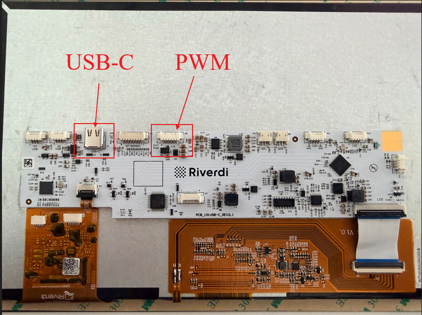
Figure 1. USB-C PCBA overview
The guide presents a simple method for changing the backlight setting using a terminal, such as PuTTY. After connecting to the device and entering the appropriate command, the backlight value can be quickly modified without using additional graphical tools. The image below shows an example configuration of the PuTTY application, which can be used to establish the connection and execute the command responsible for changing the backlight.
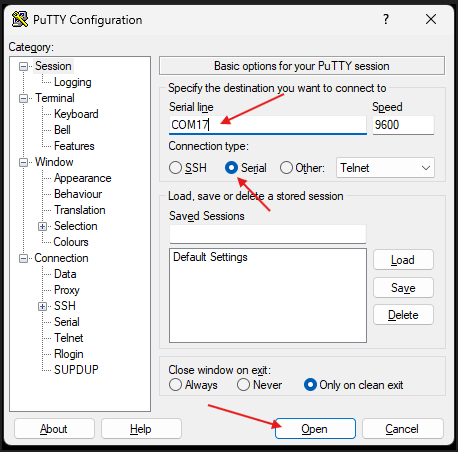
Figure 2. Terminal software example
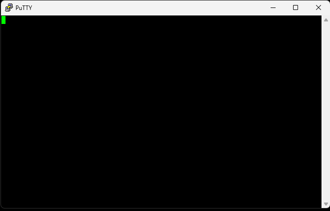
Figure 3. Putty Standard Terminal Window
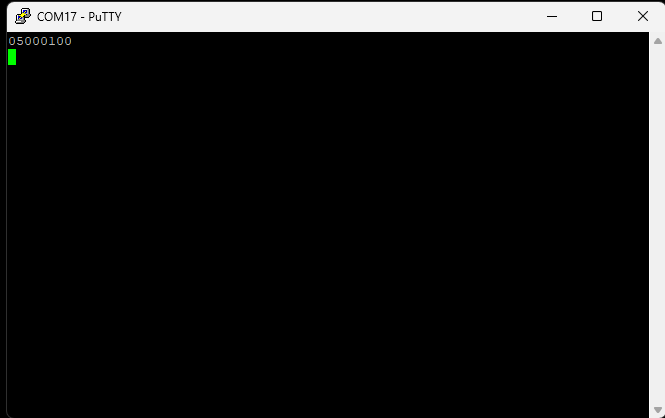
Figure 4. Device signal check. Comman 0501, result visible on image.
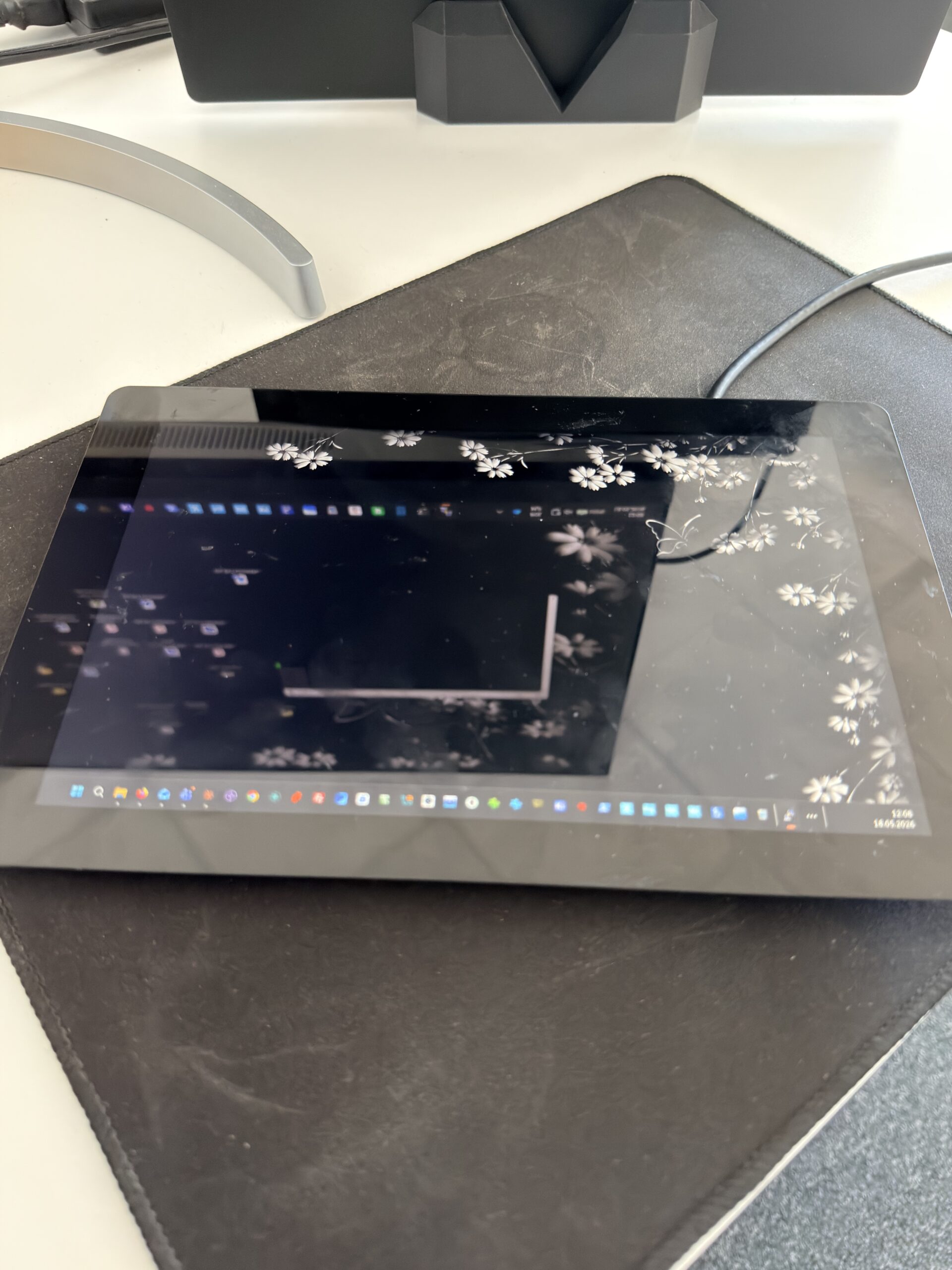
Figure 5. Backlight 10%, command 05040A, minimal value.
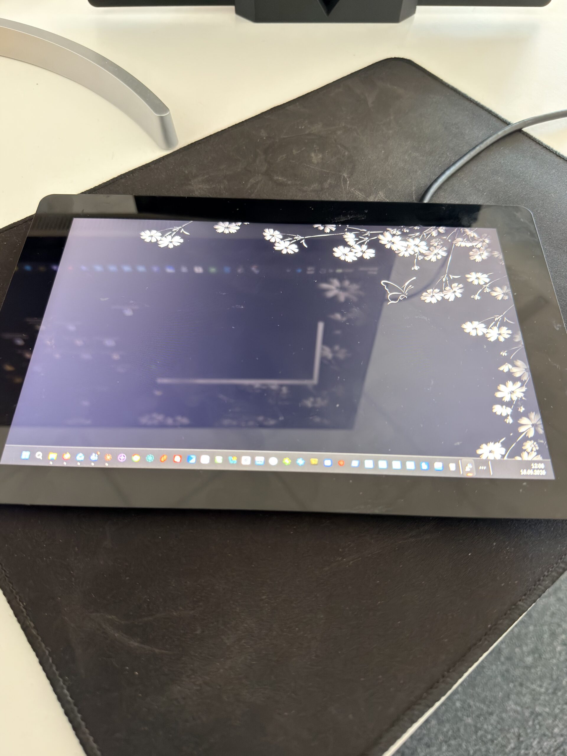
Figure 6. Backlight 100%, command 050464, max value.
DISCOVER OUR
Whitepaper
Achieve the perfect user-display interaction with the right Touch Sensor IC. Ever faced issues with phantom touch events or certification? Boost your R&D like a pro with our Whitepaper!
Go to our product catalog and see how you can save by quality, not on quality.