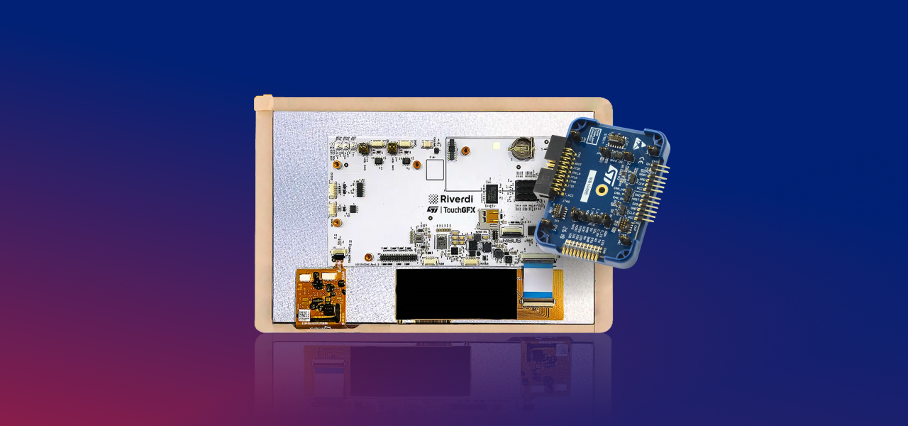
Backlight control and screen rotation are core display operations that directly impact system behavior on STM32-based designs. They are independent from application logic, but tightly connected to hardware configuration and graphics framework capabilities.
In this article, we explain how Riverdi STM32 display modules implement PWM-based backlight control using TIM15 and a dedicated LED driver, and how screen rotation is handled differently in LVGL and TouchGFX projects. The focus is on practical implementation details and architectural separation.
Backlight control on Riverdi STM32 displays
Backlight control is one of the most fundamental operations when working with embedded displays. Unlike graphics rendering or touch handling, backlight control is independent of the GUI framework and does not depend on whether the application uses LVGL, TouchGFX, or a other graphics stack.
On Riverdi STM32-based display modules, backlight brightness is controlled using a hardware PWM signal, generated by an STM32 timer.
Supported Riverdi STM32 modules
The method described in this article applies to Riverdi STM32 display modules such as:
- RVT121
- RVT101
- RVT70
- RVT50
The same principle can be used on other Riverdi STM32 platforms that expose a PWM-controlled backlight input.
Backlight control principle
In Riverdi STM32-based display modules, the microcontroller does not drive the LED backlight directly. Instead, the STM32 generates a PWM control signal, which is fed into a dedicated LED backlight driver circuit.
The backlight driver is a constant-current source, designed to regulate the current flowing through the LED strings. The PWM signal does not modulate the LED voltage directly. Instead, it controls the effective duty cycle of the driver, allowing the average LED current to vary between 0% and 100% of its nominal value.
The architecture can be summarized as follows:
- The STM32 timer (e.g., TIM15) generates a PWM signal.
- The PWM signal is routed to the backlight driver input.
- The backlight driver regulates LED current.
- he duty cycle of the PWM signal determines the effective brightness.
This means:
- PWM frequency is defined by the timer configuration
- Brightness is proportional to the PWM duty cycle.
- The LED current is always regulated by the driver, not by the MCU GPIO.
Higher duty cycle → higher average LED current → brighter display
Lower duty cycle → lower average LED current → dimmer display
Because the LEDs are driven by a regulated current source:
- brightness control is linear and stable,
- LED lifetime is protected,
- thermal behaviour is predictable,
- efficiency remains high across the operating range.
This approach provides:
- smooth brightness control,
- low power loss,
- proper current regulation of the LED backlight,
- full hardware independence from the GUI framework.
Hardware and software requirements
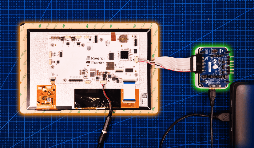
Before adjusting the backlight level, ensure that:
- the display is properly connected to the STM32 module,
- the board is connected to a PC using ST-Link,
- the project is built using a supported software template (LVGL or TouchGFX).
No changes in the GUI framework configuration are required for backlight control.
Timer used for backlight control
On Riverdi STM32 display modules, the backlight is controlled using:
- TIM15 (on both U5 and H7 infrastructures)
- Hardware PWM output
- Channel 1
The PWM configuration can be found in the project file tim.c, inside the function MX_TIM15_Init().
PWM Configuration Example
The PWM channel is configured using standard STM32 HAL structures:
sConfigOC.OCMode = TIM_OCMODE_PWM1;

sConfigOC.Pulse = 998;

sConfigOC.OCPolarity = TIM_OCPOLARITY_HIGH;
sConfigOC.OCNPolarity = TIM_OCNPOLARITY_HIGH;
sConfigOC.OCFastMode = TIM_OCFAST_DISABLE;
sConfigOC.OCIdleState = TIM_OCIDLESTATE_RESET;
sConfigOC.OCNIdleState = TIM_OCNIDLESTATE_RESET;

if (HAL_TIM_PWM_ConfigChannel(&htim15, &sConfigOC, TIM_CHANNEL_1) !=
HAL_OK)
{
Error_Handler();
}
The most important parameter here is sConfigOC.Pulse.
Brightness range and meaning
The backlight brightness is controlled by the PWM duty cycle:
- 0 → backlight OFF
- 998 → maximum brightness
Any value between 0 and 998 results in a proportional brightness level.
Runtime brightness adjustment
In addition to static configuration, the backlight level can also be changed at runtime by writing directly to the timer register:
TIM15->CCR1 = your_new_pulse_value;
This allows:
- dynamic brightness control,
- ambient light–based dimming,
- power-saving modes,
- smooth fade-in / fade-out effects.
No display reinitialization is required.
Screen rotation on STM32 displays
Unlike backlight control, screen rotation is not a purely hardware operation on STM32.
The LCD TFT display controller (LTDC) peripheral does not support image rotation, which means that rotation must be handled at the graphics framework level.
Depending on the chosen GUI framework, the implementation differs significantly.
This section explains both approaches used on Riverdi STM32 displays:
- LVGL-based rotation
- TouchGFX-based rotation
Screen rotation using LVGL
When using Riverdi STM32 display modules with RGB panels, the STM32 LTDC peripheral streams pixels from memory line-by-line. Because LTDC does not support hardware rotation, the only reliable way to rotate the image is to do it in software before the pixels reach the LTDC framebuffer.
LVGL supports display rotation via:
lv_display_set_rotation(disp, LV_DISPLAY_ROTATION_xxx);
where xxx can be 0, 90, 180, or 270.
However, this call updates LVGL’s internal coordinate system and layout handling—it does not automatically rotate pixel data for LTDC-based RGB pipelines. For that reason, the pixel rotation must be handled inside the LVGL flush callback.
Where rotation fits in the LVGL pipeline
In this setup:
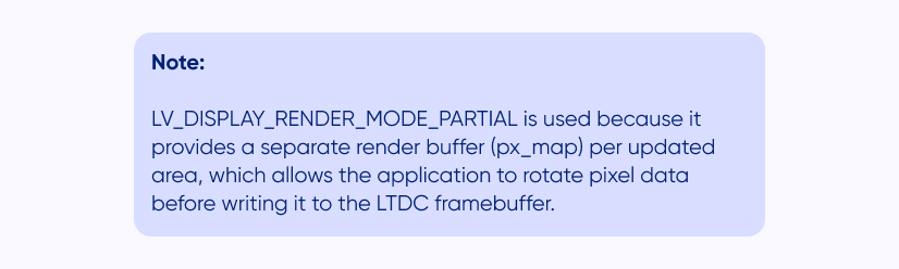
- LVGL renders small “tiles” into a working buffer (px_map) using PARTIAL render mode.
- The flush callback (disp_flush) writes the rendered tiles into the LTDC framebuffer.
- If rotation is enabled, the flush callback rotates the tile before writing it to the framebuffer.
- Touch coordinates remain consistent because LVGL knows the current display rotation.
LVGL initialization (PARTIAL rendering + rotation)
The display is created and configured in lvgl_port_display.c:
void lvgl_display_init(void)
{
disp = lv_display_create(MY_DISP_HOR_RES, MY_DISP_VER_RES);

__attribute__((section(".my_ram_d2_data")))
static uint8_t buf1[288 * 1024];

lv_display_set_buffers(disp, (void *)buf1, NULL, sizeof(buf1),
LV_DISPLAY_RENDER_MODE_PARTIAL);

/* Set the desired rotation */
lv_display_set_rotation(disp, LV_DISPLAY_ROTATION_90);

/* Register the flush callback */
lv_display_set_flush_cb(disp, disp_flush);
}
Flush callback (software rotation into LTDC framebuffer)
Below is the flush callback used for Riverdi STM32 displays with LTDC.
It supports rotation by:
- Transforming the destination area via lv_display_rotate_area(), and
- Rotating the pixel data via lv_draw_sw_rotate() before writing into the
framebuffer.
static void disp_flush(lv_display_t * display,
const lv_area_t * area,

uint8_t * px_map)
{
lv_color_format_t cf = lv_display_get_color_format(display);
uint32_t px_size = lv_color_format_get_size(cf); /* RGB565 = 2 bytes */

/* Calculate destination area after rotation */
lv_area_t rot_area = *area;
lv_display_rotate_area(display, &rot_area);

int32_t src_w = lv_area_get_width(area);
int32_t src_h = lv_area_get_height(area);

uint32_t src_stride = lv_draw_buf_width_to_stride(src_w, cf);
uint32_t fb_stride = lv_draw_buf_width_to_stride(MY_DISP_HOR_RES, cf);

/* LTDC framebuffer address */
uint8_t * fb = (uint8_t *)hltdc.LayerCfg[0].FBStartAdress;
fb += (rot_area.y1 * fb_stride) + (rot_area.x1 * px_size);

/* Cache maintenance (required when framebuffer is in external SDRAM) */
SCB_CleanInvalidateDCache();

lv_display_rotation_t r = lv_display_get_rotation(display);

if(r == LV_DISPLAY_ROTATION_0) {
/* Fast path: no rotation */
for(int32_t y = 0; y < src_h; y++) {
lv_memcpy(fb, px_map, src_stride);
px_map += src_stride;

fb += fb_stride;
}
} else {
/* Rotate the rendered tile directly into the framebuffer */
lv_draw_sw_rotate(px_map, fb,
src_w, src_h,
src_stride, fb_stride,
r, cf);
}

/* Notify LVGL that flushing is complete */
lv_display_flush_ready(display);
}
Result
With this approach:
- the image is physically rotated before LTDC output,
- LVGL layout and rendering remain consistent,
- touch coordinates stay aligned with the rotated UI,
- no changes to LTDC timing configuration are required.
Screen rotation on STM32 using TouchGFX
In contrast to LVGL, TouchGFX handles screen rotation at the framework and configuration level. For most STM32-based Riverdi display projects, rotation can be enabled without modifying low-level display drivers or framebuffer handling code.
This makes TouchGFX particularly convenient when:
- the display orientation is known at design time,
- rotation does not need to be changed dynamically at runtime,
- a fast and maintainable configuration-based approach is preferred.
TouchGFX rotation concept
TouchGFX abstracts the display pipeline and manages:
- framebuffer layout,
- rendering orientation,
- coordinate transformations,
- touch input mapping.
As a result:
- no manual pixel rotation is required in the LTDC flush path,
- no custom framebuffer manipulation is needed,
- rotation is applied consistently across rendering and touch input.
Enabling screen rotation in TouchGFX designer
Screen rotation is configured directly in TouchGFX Designer.
The exact naming may differ slightly depending on the TouchGFX version, but the
workflow is consistent.
Step 1—Open Display Configuration
In TouchGFX Designer:
- Open your project.
- Navigate to the Display / Board / Application Configuration section.
- Locate the Display Orientation or Screen Rotation setting.
Summary
On Riverdi STM32 modules, backlight brightness is controlled by hardware PWM generated by TIM15 and regulated by a constant-current LED driver. The duty cycle defines brightness, independent of the GUI framework, enabling stable and predictable operation.
Screen rotation is not supported by LTDC hardware and must be handled at the graphics layer. In LVGL, rotation requires software pixel transformation in the flush callback. In TouchGFX, rotation is configured at the framework level without modifying low-level display drivers
Separating hardware-level control from graphics-layer responsibilities ensures clean architecture and reliable behavior in STM32-based display systems.
DISCOVER OUR
Whitepaper
Achieve the perfect user-display interaction with the right Touch Sensor IC. Ever faced issues with phantom touch events or certification? Boost your R&D like a pro with our Whitepaper!
Go to our product catalog and see how you can save by quality, not on quality.