Table of Contents
What SPI is and where it is used
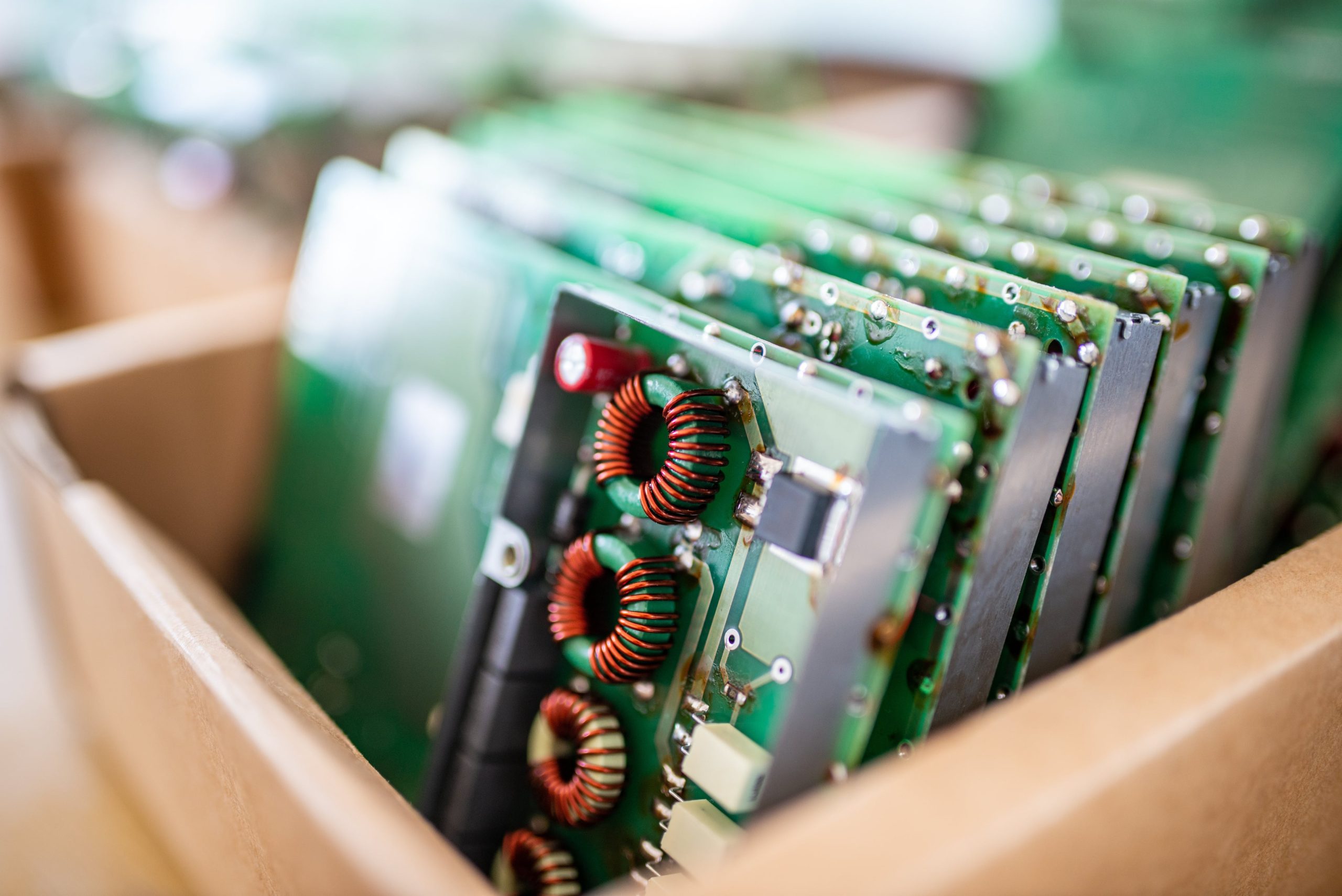
SPI (Serial Peripheral Interface) is a synchronous serial communication protocol widely used in embedded systems for high-speed, short-distance data exchange.
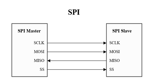
It operates with four main signals:
- CLK – clock generated by the master
- MOSI – data sent from the master to the slave
- MISO – data sent from the slave back to the master
- CS – chip-select line to enable the target device
SPI is popular because it is simple, fast, and requires low overhead.
It is commonly found in:
- Display and touch controllers
- External flash memories
- ADCs, sensors, and DACs
- Bridge ICs and peripheral expanders
- Microcontroller-to-coprocessor communication
Its predictable timing and full-duplex nature make SPI ideal for devices that require tight control and quick data transfers.
Tools used to debug SPI communication
When investigating SPI issues, engineers typically rely on a combination of hardware and software tools:
Logic analyzer
The most important tool.
It shows the exact timing of CLK, MOSI, MISO, and CS and allows you to decode transactions.
A 10–20 EUR analyzer is enough for most SPI debugging tasks.
Oscilloscope
Useful when signal integrity is in question — ringing, overshoot, slow edges, noise, or grounding problems.
Firmware debugger / Logging
The MCU’s debug console can help verify that correct initialization sequences and commands are being sent.
Reference board or development kit
Connecting the display to a known-good platform (e.g., Riverdi’s STM32 Evaluation Board) helps confirm whether the issue is on the MCU side or the display side.
Datasheet and register map
A crucial “tool.”
Knowing what ID or status registers a device should return makes verification straightforward.
With these tools, almost any SPI problem becomes visible and testable.
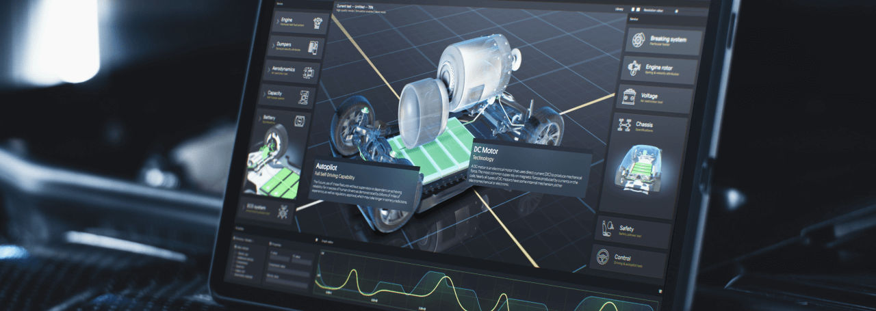
Why and how SPI is used in Riverdi EVE displays
SPI remains an important interface across several Riverdi product families. Depending on the module, SPI may be used for:
EVE graphic controllers
Bridgetek BT81x/BT82x controllers rely on SPI for command transfer, display list updates, register access, and event data.
SPI is the primary link between the host MCU and the EVE engine.
External flash memory (QSPI/SPI Flash)
Many Riverdi modules include external flash used for:
- graphical assets
- fonts
- image data
- UI resources
Programming and retrieving these assets requires SPI communication.
Driver and bridge ICs
Some adapter boards and display subsystems include SPI-controlled peripherals for:
- power sequencing
- LED backlight control
- register configuration
- status monitoring
In these designs, SPI provides predictable control and simplifies integration with common MCU families such as STM32, ESP32, NXP, and Renesas.
How to debug SPI communication on Riverdi displays
1. Verify wiring and pinout
Check CLK, MOSI, MISO, CS, and GND carefully against Riverdi datasheets or RiBUS documentation.
Incorrect grounding or swapped lines are the most frequent causes of failed communication.
2. Check reset / power-down sequencing
Riverdi modules may require specific power-up behavior:
- PD or RESET must be driven correctly after power is applied
- timing delays (20–50 ms) must be respected
- modules should not start receiving commands before reset is released
If sequencing is incorrect, SPI devices will not respond.
3. Confirm SPI mode and clock speed (CS)
Most Riverdi SPI-based components use:
SPI Mode 0 (CPOL = 0, CPHA = 0)
Initial communication should be kept at 1–2 MHz to ensure stability.
Too high a clock speed during startup often leads to silent failures.
4. Test communication with a known register
Every SPI subsystem has an identification or status register.
Reading this register is the quickest way to confirm that wiring, SPI mode, and timing are correct.
Examples:
- EVE: device ID
- SPI Flash: JEDEC ID
- Bridge ICs: driver code or control register
If the returned value is incorrect, the problem is almost always wiring, reset, or SPI configuration.
5. Use a logic analyzer for final confirmation
Verify that:
- CS goes low during transactions
- CLK edges are clean
- MOSI matches transmitted data
- MISO changes during read commands
- RESET/PD transitions occur correctly
A 10–20 EUR analyzer can reveal issues instantly.
6. Compare against a known good setup
If you have access to the Riverdi STM32 Evaluation Board, connect your display there:
If it works, the problem is not in the display.
If it doesn’t, it confirms a connection or hardware issue.
DISCOVER OUR
Whitepaper
Achieve the perfect user-display interaction with the right Touch Sensor IC. Ever faced issues with phantom touch events or certification? Boost your R&D like a pro with our Whitepaper!
Go to our product catalog and see how you can save by quality, not on quality.